|
Features
|
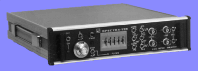
H212 Dual Pulse Generator
The H212 Dual Pulse Generator and Flow Meter Simulator is a special purpose instrument designed to provide a dual pulse train which can be used, for example, in the testing and commissioning of flow metering systems. Its principal function is to generate a variable frequency pair of pulse trains which can represent the outputs of a flow meter.
A batch control system is included which permits a preset quantity of pulses to be delivered over a wide range of frequencies. Several front panel switches allow a variety of operational and fault conditions to be simulated, so that dual pulse security systems may be fully exercised.
The H212 is a ruggedly built, portable test instrument which can be powered either from external 110/230V a.c. mains or from its own built-in, rechargeable nickel-cadmium batteries.
High security flow measuring systems employing typically dual-pulse transmission to IP252/76 Level 'A' Section 1 Part XIII require elaborate testing to ensure that they are functioning properly. The H212 is a portable simulator for such systems which can be used to represent flow meter output under all normal or fault conditions. Although the instrument was originally intended for turbine meter simulation it is equally useful in Vortex, P.D. and other applications.
A voltage controlled oscillator, whose frequency is adjusted by a ten-turn potentiometer, is started and stopped by a simple digital batch control system. The number of pulses to be delivered is set on five decade thumbwheel switches and the batch is started by pressing the start button. The VCO now generates at the frequency set on the ten-turn pot and counts down a five decade counter from the pre-loaded number on the thumbwheels. When the counter reaches zero the VCO is turned off. The batch control system may be overridden by a simple run/stop switch which directly controls the VCO.
The pulse output of the VCO feeds a phase-splitter which delivers two separate pulse streams to the output channels A and B. The relative phase of these two outputs can be set to 0°, 90°, 180° and 270° by front panel switches, thus variable-frequency variable-quantity, variable-phase outputs are achieved.
To simulate the effect of a missing blade in a turbine meter a 1-in-10 pulse drop-out sequence can be switched into either or both output channels. The timing is arranged so that the instant of drop-out is never simultaneous on both channels, it is always five pulses away from the opposite channel. The drop-out control is unaffected by the pulse controls and vice-versa.
In applications where electro-dynamically induced turbine meter signals are being simulated, it is convenient to be able to add one extra pulse to the batch. This compensates for the single pulse which is lost during the start of a new pulse delivery because of the necessity of having a low frequency cut-off in the logic. The simulator is equipped with a +1 pulse switch which increases the delivered batch quantity by one.
Each output channel A and B is equipped with a 12V CMOS pulse output BNC socket and a 12V differential line driver output. Each differential line may be open-circuited by a switch to simulate line failure.
Rear terminals provide power pulses to drive up to eight dual-pulse systems.